
Game Dev Maths #0 - Intro & Coordinate Systems
- Abby Karnstein
- Mar 2
- 10 min read

Updated: Mar 3
Due to both the genuinely overwhelming amount of AI pop ups on here and the limited space for files, I will be continuing this series and all other blog posts over on Medium.
If you want to develop games, you generally need to have some understanding of maths, particularly things like transforms. Anything you place in the world, be it an NPC or a HUD element contains position data and the ability to be manipulated by maths. All the numbers we use are known as 'real' numbers- that is, besides the imaginary numbers used by quaternions, but don't think about that just yet. A real number is anything you could conceivably put on a number line, like how the fraction 2/3 would be placed closer to 0 than √16. Real numbers, regardless of notation, can theoretically stretch to infinity.
We encounter a mismatch between the real world and the computer generated one almost immediately, however. If I want to travel in one distance forever, or count to infinity, I sort of can (theoretically (you will get sick of this word before the end of the article)), but a computer has bounds and limitations that come in many forms, and they need to be adhered to in order to get anything done. The type of numeric data you'll tend to work with are floats and ints, though we have shorts, half-floats and doubles also. The words integer and int are typically used interchangeably, for obvious reasons, but shorts are integers as well.
Integers are whole numbers, or 'natural' numbers, ints are usually in a 32bit format, and can store 4,294,967,296 different values, including 0. You may encounter terms like signed or unsigned int, wherein the former can hold negatives and the latter cannot. This means unsigned can use a range of 0 to 4,294,967,295, while signed uses −2,147,483,648 to 2,147,483,647. In contrast, the short is a 16bit integer that can store 65,536 different values.
Floats are rational numbers, or fractions, which are represented through the use of decimal points. We can also call them singles, or single-precision. They are also 32bit, with half-float being our short equivalent and double being a huge 64bits. Unsurprisingly they also have signed and unsigned variants. Positions in game engines use floating-point numbers for accuracy and precision, something that could only move via whole numbers would end up looking like they were doing so at a low frame rate.
Lastly, there are so-called irrational numbers, things like φ and π, with an infinite number of decimal places. Our time and energy being finite, however, necessitates that we usually settle for about eight. Most often, we use Pi in trigonometry functions, where it also finds its place in game dev, and Euler's e exponential wherever a multiply won't quite cut it. Real numbers are the backbone for most engineering disciplines, though they are by nature uncountable, to the extent that studying them is known as continuous mathematics, where their finite counterparts are discrete.
2D Coordinates
2D maths, particularly vector maths, can be represented often with the Cartesian coordinate system, which is another way of saying rectangular, honestly. We work from an arbitrary point in space, which we call (0,0) and deduce values from the distances along two perpendicular axes (the length of which can, again, theoretically be infinite). When you open a game engine level, the start point of world zero will have already been decided for you. Even in 3D games there is frequent use of 2D, most obviously because you play on a two dimensional screen, but namely UV space for shaders and meshes. Of course fixtures like compasses and maps can also use 2D coordinates, which denote positions of all UI elements on the screen, or use the players vector on a 2D plane to orient.
When we talk about position data, in this case (x, y) the numbers represent how far a point is from the respective axes. A coordinate of (84, 2) will have a lot of distance between itself and x, but maintains a close relationship with y. To bring back the concept of signed/unsigned, the coordinate value represents the signed distance of a point, since I could also have a position of (-84, -2).
The below gif illustrates negative and positive position values, where green is our Y and red is X. Positive values for both give us yellow, while negative is black.

If we look at ShaderToy's default code, we can see an example of 'normal' 2D coordinate space that we're generally quite familiar with, where we have (0,0) in the corner, rather than the middle. The top right is considered (1,1), and by default we have no negative values. Keep in mind that this is a coordinate space (screen space) using a 2D coordinate system, more on that later.

void mainImage( out vec4 fragColor, in vec2 fragCoord )
{
    // Normalized pixel coordinates (from 0 to 1)
    vec2 uv = fragCoord/iResolution.xy;
    // Output to screen
    fragColor = vec4(uv,0.,1.0);
}
For certain effects, like a vignette, we might find it easier to work from the centre instead, where the bottom left is (-1,-1). Changing to a (0,0) centre requires multiplying by 2 and subtracting 1. This is covered more elaborately in my other post about shader code.
void mainImage( out vec4 fragColor, in vec2 fragCoord )
{
    // Normalized pixel coordinates (from 0 to 1)
    vec2 uv = fragCoord/iResolution.xy * 2.0 - 1.0;
    // Output to screen
    fragColor = vec4(uv,0.,1.0);
}
However in Unreal Engine, our (0,0) is the very top left and (1,1) the bottom right, a bit like where you would start and end reading the page of an English language book, or (more accurately) the tiles of a map. This doesn't inherently pose a problem for us: no matter which orientation our X and Y axes, the coordinate space can be rotated to 'normal' orientation (if we need it to be), with X pointing right and Y pointing up. For several reasons that I'll cover further down in this post, this is not the case in 3D.


The above manipulation of the point (0,0) is a way of altering the position of something that is dependent on the underlying coordinates to orient itself. I am not changing the position of the square, I am changing the coordinate origin.
Think of B as the coordinate origin position and A as the threshold. If A was 0.1, the square would be twice as big.
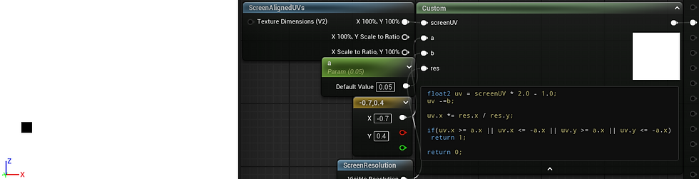
float2 uv = screenUV * 2.0 - 1.0;
uv.x *= res.x / res.y;
uv -=b;
if(uv.x >= a.x || uv.x <= -a.x || uv.y >= a.x || uv.y <= -a.x)
  return 1;
return 0;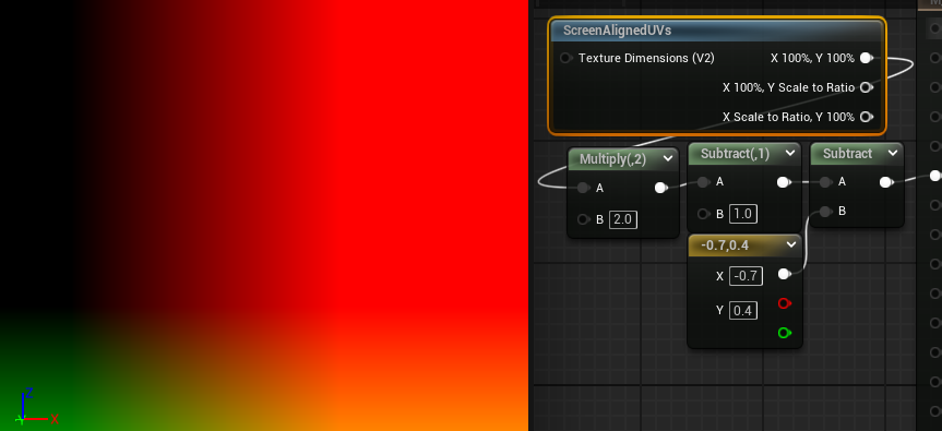
If we create a new variable with reference to the UV before we offset with b, we will retain access to the original UV for use as well, as can be seen here with the uv0 variable. Offsetting or otherwise transforming the UVs for a particular use case doesn't mean you have to use the transformed coordinate space for everything going forward, and layering them can give access to many unique effects.

So, if we can understand the space textures occupy, that they are mapped via 2D coordinates, we can mask out, colour, move and generally manipulate pixels (or vertices!) based on their position in space.

float4 exampleTex = Texture2DSample(texObject, texObjectSampler, uv);
if(uv.x<=0.5 && uv.y <= 0.5)
  exampleTex *= float4(0.5,0.5,1.0,1.0);  //green outlined section
else if(uv.x>=0.65 && uv.y >= 0.2)
  exampleTex *= float4(0.5,.5,.5,1.0);    //blue outlined section
return exampleTex;
float2 uv0 = uv;
float2 uv1 = uv;
float ang = t * 3.14 * 2;
float2 ang1 = float2(sin(ang), cos(ang));
float2 ang2 = float2(cos(ang), -sin(ang));
float2 dotProd = .5 - uv;
float dot1 = dot(dotProd, ang1);
float dot2 = dot(dotProd, ang2);
float2 origin = float2(dot1, dot2);
uv0 *= 5 + cos(t); //tile
uv1 += t; //offset
float2 uv2  = .5 + origin; //rotate
float4 exampleTex = Texture2DSample(texObject, texObjectSampler, uv);
float4 exampleTex0 = Texture2DSample(texObject, texObjectSampler, uv0);
float4 exampleTex1 = Texture2DSample(texObject, texObjectSampler, uv1);
float4 exampleTex2 = Texture2DSample(texObject, texObjectSampler, uv2);
if(uv.x>=0.5 && uv.y <= 0.5)
  return exampleTex0;
else if(uv.x<=0.5 && uv.y >= 0.5)
  return exampleTex1;
else if(uv.x>=0.5 && uv.y >= 0.5)
 return exampleTex2;
return exampleTex;
A Note on 3D Coordinates
3D coordinate space is much harder to easily visualise than 2D, perhaps more so than you would expect. It's a bit like upgrading from playing traditional chess into whatever this is:

In 3D, all three axes are perpendicular to one another, with the new Z axis either functioning as our height or our depth, depending on the software. We can think about the layout two dimensionally by working off of the xz, xy or yz planes, where the omitted axis is what the plane runs perpendicular two, as shown below.
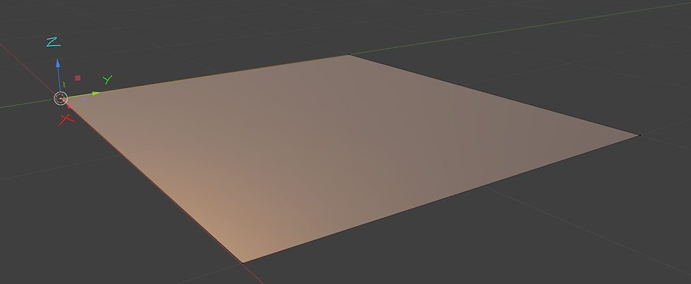
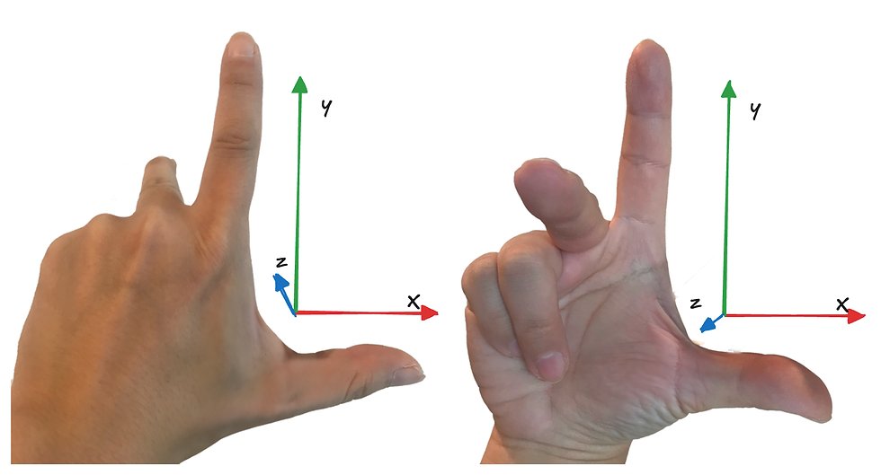
While principally the planes work the same as 2D, I mentioned before that 3D axes cannot be rotated to align the same way that 2D can. This is because 3D space will use either a left or right handed coordinate system, and is likely why your models face the wrong way importing between software. A right handed system, like Blender above, will rotate counter-clockwise with positive rotation, while a left handed system will move clockwise. To understand why it's called this, extend your thumb and index fingers like you forgot which one left is, or think the person in front of you is a loser. This is your X and Z axes. Point your index forward to make the Y. You will notice no matter what way you orient your hands, there is no way for all 3 axes to point in the same direction short of breaking a digit- one axis will always be flipped.
Coordinate Systems vs Coordinate Spaces (yes there's more im so sorry)
As mentioned many times, our 3D coordinate system is theoretically infinite, so we could use it for pretty much whatever we want- it will always have the right units to ascribe. But that doesn't mean it's the easiest to work with. We have already touched on screen space above, and while you may for masochistic reasons want to use world space to always keep an object on a point of the screen, you will find working in screen space (or the marginally different but mostly the same camera space) significantly easier.
We also have local space, sometimes called object space, tangent space, camera space, instance/particle space and view space. If we want to do maths between two vectors, one in world space and one in local space, for example, we will first need to transform one of them so they use the same coordinate space. This can be a bit nebulous, so I'll save it for the vector post.
Local/Object Space
Each object, unsurprisingly, has it's own independent object space, the transform of which follows the object it's attached to. If I rotate something in world space, the object space transform will move with the object, much like we each move with the rotation of Earth, but I'm still quite capable of turning on the spot and moving in my new 'forwards' direction, in the event I encounter an axe murderer or Sharon Osbourne.
If I have two NPCs and I want them to each walk forwards but one is facing west and one south, absolute world coordinates are going to be a much bigger headache than local space, in the same way 'go north' is not a helpful direction to give your driver at a T junction.
To touch briefly on the graphics pipeline, 3D models can exist in 3D space because the computer (more specifically the GPU) knows the position of each vertex in object space, and then transforms them into screen projection space. It uses these points to draw triangles between them in a process called primitive assembly, and is only possible because the computer knows that vertex A is 6 units to the left of vertex B, and so on. All of that to say, coordinate spaces are quite important.
Tangent Space
This consists of the normal, binormal and tangent. Each vertex has its own set of coordinates to be accessed, and it's used to determine lighting, effects like fresnel or Z masking, and, of course, normal maps. The binormal can also be called the bitangent.

This is the reason why normal maps look the way they do. The amount of red or green a pixel in your normal map has is direction data- your high poly mesh has a lot of polygons, and each of them face a certain direction. A normal map is a way of storing those directions, so that when things like lighting are calculated the GPU knows if it's facing towards the light, or away from it. As for the blue map... well, it's not actually doing much more than being filler. Many games of old have packed another mask map into the blue channel of the normal rather than waste 8bits on interpolation, though it can reduce the quality of normals somewhat, and wont be used for photorealism much.
The existence of transform data per vertex can be incredibly useful, and vertices in general are great little information storage units. Fresnel and dot product effects work because we have the normal telling us which vertices are pointing towards us, and at what angle. In many ways this can make working with normal maps and certain shader vertex transforms more challenging, as it's likely tangent space will need to be appropriately transformed into something like world or local space first.
Camera Space
Camera space is different to screen space pretty much because it's 3D, not 2D. The camera can access depth in the frame and determine if an object is behind another object, thereby removing the need to render it, if something is even on screen at all and by how much, and at what distance from us it should begin obscuring everything in Silent Hill 2 style fog.


Instance/particle space is pretty much a per instance transform that allows every particle in a Niagara system to have it's own gizmo and feel special, allowing for non-uniform transforms of each instance in a system, otherwise they'd all be using the same object space gizmo at the origin, which would make VFX extremely boring. Graphics programmers would be able to tell you that there is a subtle but important difference between screen space and view space, but I am not smart enough to explain it and I have pontificated quite enough for one post.
Thank you for reading ! (even if i made you do so), the next article will cover vectors.
Please let me know if you find any typos, inaccuracies, or man door hand hook car door in the article and I will update accordingly :)


Comments